
Why steam turbines fail—and how to prevent it
This article originally appeared in Modern Power Systems.
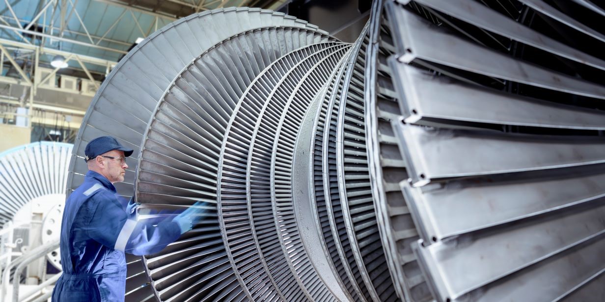
Steam turbines are critical components in power generation and various industrial processes, but despite advancements in design, materials and maintenance practices, steam turbine failures continue to occur. Often these failures result in substantial unplanned downtime, equipment damage, loss of generation and business impact.
Steam turbines are designed to operate within specific parameters. These include temperature, pressure, steam quality/purity, vibration, and operating profiles. Deviating from the design parameters can increase stresses, accelerate component degradation and be a precursor to mechanical failure mechanisms.
This article examines failure trends FM has seen, focusing on the three most common root causes. It also outlines practical strategies for risk mitigation, aiming to enhance reliability, extend equipment life, and reduce operational disruptions.
What are some of the key loss drivers for steam turbines?
Flow path component damage
Flow path component damage remains one of the leading causes of steam turbine failures. These failures are often attributed to domestic object damage (DOD), originating from internal component failures, and foreign object damage (FOD), caused by external debris entering the turbine.
While the initial failure may be localized, damage to downstream components can be extensive, often resulting in prolonged outages and costly repairs.
Contributing factors include thermal/cyclic fatigue, high/low cycle fatigue, creep, impact damage, corrosion, erosion and inadequate foreign material exclusion programs.
Many steam turbines operate within a challenging energy market. As a result, they are experiencing faster ramp-up rates, low load operation and two shifting. This is elevating stresses experienced by critical components and contributing to some of the factors listed above.
Two shifting is required to meet electricity peak demand. This mode of operation significantly impacts operational integrity by accelerating component degradation. This can lead to increasing thermal stresses and fatigue, resulting in premature mechanical failure and contributing to domestic object damage.
Low load operation is required when demand is low. This supports grid stability and allows rapid load increases. However, running at low load can lead to inefficiencies, increased heat rate, and heightened susceptibility to fatigue. These conditions can degrade performance and reduce the turbine’s operational lifespan.
Maintaining precise water chemistry and steam purity is essential. Inadequate water treatment or contamination can result in corrosion, scaling, and deposits, all of which impair turbine efficiency and reliability. Corrosion can also contribute to component failure and subsequent domestic object damage. In particular, it can lead to pitting and evolve into stress corrosion cracking (SCC). This is a severe failure mode that occurs under tensile stress in corrosive environments. The last-stage blades are highly susceptible due to their exposure to wet steam and high tensile loads.
Some measures to mitigate flow path component damage include:
- Implementation and enforcement of a robust Foreign Material Exclusion (FME) program, extending to all systems feeding into the turbine. Reviewing and auditing of the program including regular inspections should be performed to verify compliance.
- Operating within design parameters. Any deviations should be fully reviewed with the OEM or third-party specialists. Changes must be documented through a formal Management of Change (MoC) process, including relevant process hazard studies.
- Continuous review and update of the maintenance plan, based on findings from unplanned events and outages.
- Use of OEM approved parts or having a thorough review procedure for third party components to ensure they meet or exceed the original design specification.
- Monitoring and maintaining water chemistry and steam quality, with predefined action plans for responding to chemistry excursions.
- Having a robust outage management program, including part inspection and quality control procedures.
- Implementation of relevant customer information bulletins from the OEM. These indicate that an issue has likely occurred on a similar steam turbine.
Bearing damage
Journal and thrust bearings support the axial and radial loads of the steam turbine rotor. Journal bearings use a hydrodynamic oil film to minimize friction and reduce heat during high speed rotation. Thrust bearings, typically tilting pad types, maintain axial positioning against pressure induced forces.
There are multiple damage mechanisms, such as misalignment, overheating, poor oil condition, vibration, and loss of lube oil. Based on FM loss history, the most prominent failure mode is a loss of lube oil. This is often caused by oil contamination, loss of oil supply or improper oil viscosity, all of which can lead to potential metal to metal contact.
Direct current (DC) lube oil systems are critical to protect against the loss of lube oil. These typically operate on low oil pressure due to loss of alternating current (AC) lube oil pumps, and provide a safe run down of the steam turbine.
FM’s loss history shows numerous instances in which DC systems have failed to operate. These failures often result in wiping of the babbitt material on bearing surfaces and damage to the turbine rotor. Causes frequently include inadequate maintenance and testing of the battery system. In some instances, specific requirements within the operating logic have prevented the operation of DC lube oil pumps.
Some measures to mitigate bearing failures include:
- Regular sampling and analysis of the lube and control oil, taking corrective actions to maintain optimal oil quality.
- Implementation of rigorous quality assurance (QA) and quality control (QC) procedures during maintenance activities to ensure proper installation and alignment.
- Regular testing of the DC lube oil pumps and ensuring that a suitable battery maintenance strategy is in place and followed.
- Performing frequent trend reviews of the bearing temperatures and vibrations.
- Ensuring that the emergency DC lube oil pump discharge bypasses the oil cooler and filter.
- Removal of the thermal overload protection for the DC lube oil pump motor to prevent the pump from tripping during an emergency event.
- Removal or locking open of any valves that are present on the AC and DC lube oil pump discharges. This should be managed using a lock out tag out type permit system.
Motoring and overspeed
Among the most critical undesired operating events in steam turbine generator systems are motoring and overspeed. Both can lead to severe mechanical damage and extended unplanned outages. FM’s loss history shows that the initial response by plant operators has a major influence on whether damage can be limited or prevented.
Motoring occurs when the generator circuit breaker fails to trip during a reverse power flow condition. In this scenario, power is imported from the grid, effectively turning the generator into a motor. If the steam valves are closed, as is often the case during shutdown, the cooling properties from steam flow are lost. This leads to windage, where rotating components overheat due to friction with residual air or steam. As temperatures rise, thermal expansion can cause blade-to-casing contact, resulting in severe rubbing, blade liberation, and extensive damage to shaft line components. The most effective mitigation is to immediately open the generator circuit breaker (or a relevant downstream breaker) to stop the motoring condition.
Overspeed occurs when steam is inadvertently admitted into the steam turbine while the generator is disconnected from the grid. With no electrical load to resist rotation, the turbine accelerates rapidly. The resulting centrifugal forces can exceed design limits, leading to blade liberation, rotor imbalance, and subsequent shaft line component damage.
FM loss investigations have shown that distinguishing between motoring and overspeed is critical. If operators focus on the steam valves during a motoring event, the turbine will continue to motor. If operators trip the circuit breaker whilst steam is still being admitted to the turbine, it may cause an overspeed event.
Some ways that motoring and overspeed can be mitigated include:
- Development of clear and concise emergency operating procedures.
- Performing scenario-based training across shift teams to reinforce correct response protocols.
- Periodic electrical testing on the critical circuit breakers and relays to ensure reliable operation.
- Overhaul and inspection of the steam turbine valves at OEM recommended intervals to ensure proper sealing and actuation.
- Carrying out of overspeed protection testing at the relevant frequencies and maintenance of all safety related equipment.
What other guidance is available?
Findings from the steam turbine data analysis, engineering best practice and industry learnings feed into FM Property Loss Prevention Datasheet, Steam Turbines, 13-3. Further guidance and risk improvement suggestions are included to support the mitigation of a large loss at your locations.
FM data sheets